CAD doctor not only supports the whole process of product from design to manufacture, including analysis, rapid prototyping and assembly, but also provides strong support for the application of 3D data in different fields, such asaerospace, military industry, high-speed rail, automobile, ship, high-tech, medical, computer graphics, equipment installation and so on.
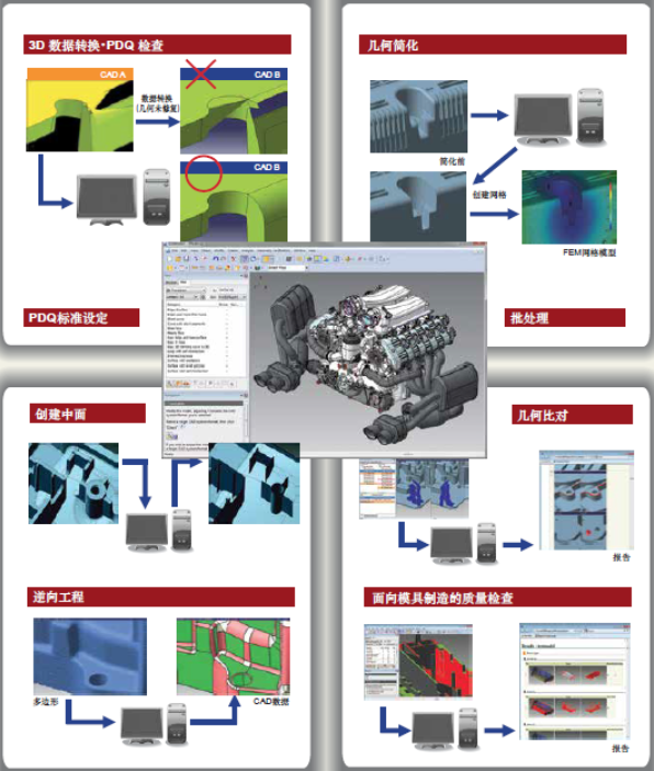
1、Data Quality Management
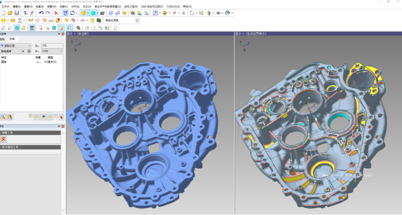
Recognition and Visualization of PDQ Errors
CADdoctor has 30 years of experience in the field of data conversion. It can meet the requirements of automobile, aerospace industry and international standards. CADdoctor allows execution of MILSTD/ISO/VDA/SASIG/JAMA/JAPIA based on PDQ. CADdoctor can automatically detect and list all errors in the window, and highlight the error area on the 3D model.
Automatically fix PDQ errors
Geometric errors in most CAD data can be detected by PDQ error detection. A simple click on the "auto-repair" action can perform the auto-repair process. CADdoctor summarizes many years of experience in geometry/topology repair under the premise of non-manual operation. It has a high-precision technology to automatically determine the geometry or position of edges and surfaces in the original CAD system. At the same time, all the repair mechanisms of the CAD doctor will ensure consistency with the original data.

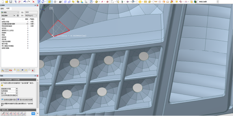
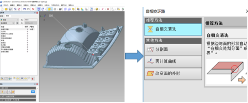
Interactive Intelligent Repair of PDQ Errors
The Interactive Intelligent Repair function is designed to handle the extremely serious errors that remain after the automatic repair is executed. When the user selects the error in the work panel, the system automatically displays the recommended interactive repair options. The user can select the error one by one and use the repair command to perform the repair. The navigation function of the CADdoctor can guide users to select repair commands for different types of errors. These functions enable each CAD engineer to fix extremely serious data geometry errors that cannot be fixed without a CAD doctor.
2、Geometric Simplification/Medium Surface Creation
Automatic feature recognition and removal
Geometric simplification can reduce the complexity and file size of the model by removing design features that are not required for downstream processes.

Feature recognition
Feature recognition can automatically distinguish features such as inverted circle, hole, circular platform, stiffener and step. CADdoctor can support feature display and classification integrated with user interface. CADdoctor uses nondestructive technology to remove features without breaking the geometric quality of the original model. The feature removal object can be a set of features or a class of features selected by the end user by clicking on the mouse. Once the feature is removed, the adjacent surfaces will be extended and intersected to repair.
Feature removal
All the identified features can be removed at one click, and of course the user can decide to ignore some of the identified features. Once a feature is removed, the adjacent surface is extended to fill the removed surface. Sometimes the feature removal results in abnormal results, such as self-intersection. In this case, the system will restore the original features to ensure the consistency of the model data.
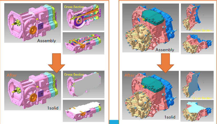
Physical encapsulation
Entity encapsulation creates a very lightweight entity model by merging all components within the assembly and deleting detailed internal geometries.
Entity encapsulation is mainly used in two cases: intellectual property protection and lightweight data. This requires encapsulation to ensure geometric accuracy and greatly lighten model files by reducing the number of internal entities and file size. CADdoctor can carry out system automation processing and user instruction operation for large assemblies with complex geometry to perform entity encapsulation operation.
The encapsulated entity creation process involves creating a single entity by combining complex assemblies with Boolean operations. CADdoctor automatically detects and repairs imperceptible defects. Automatic defect detection and repair can strictly control the encapsulated results according to user-defined shape and parameters to be retained. Combined with feature search and removal functions, users can better control the results of internal detailed design.
Middle face generation
CADdoctor provides middle face creation tools to create middle face based on high-quality entity models for CAE analysis. It also provides a wealth of repair capabilities to allow the repair of intermediate surfaces for complex solid models.
Automatically create the middle surface
A CADdoctor can create an intermediate surface by user-defined parameters at the middle point, front, and back. Advanced settings support uneven thickness including surface steps and surface gradient changes. The settings created through the middle face support the creation of isolated middle face with different wall thicknesses through ribs and bulges.
Modify the middle surface
The CADdoctor includes tools for repairing the middle face. Users can modify the generated middle face according to the initial results and meet the actual situation or downstream requirements.
3、Polygon/Reverse Engineering
Creation, Inspection and Repair of Polygon Data
Polygon data are mainly used for visualization, computational fluid dynamics, digital models and rapid prototyping.
CADdoctor supports the rapid parameterization of point cloud data or CAD data to precisely create polygons relative to the original 3D data set.
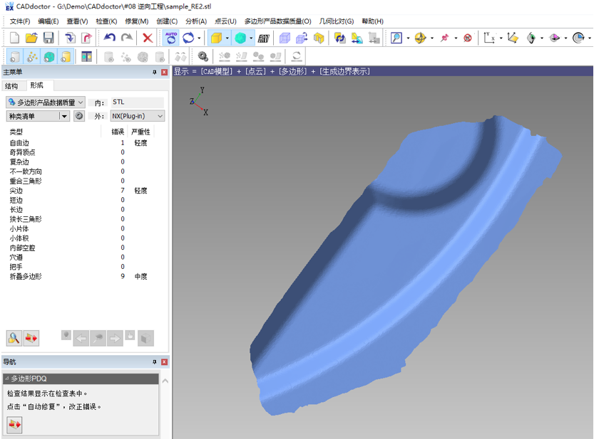
Reverse Engineering
3D reverse engineering tools can create B-rep geometry from data acquired by 3D scanners. CADdoctor supports the creation of CAD models from 3D point cloud data or polygon data.
Automatic identification of inverted circle, datum and analytic surface
The CADdoctor reverse engineering module can automatically identify the inverted circle and the reference area by curvature of polygon. High-quality B-rep data containing the same surface structure and surface type are created by identifying plane and cylinder surfaces. The quality of B-rep data is equal to the result of direct modeling on the CAD platform.
Users can easily adjust the corner recognition area by scrollbar operation to ensure that the automatic recognition of the corner is in line with the design intent. At the same time, the user can specify the radius of the corner to identify the corner in a specific range for rapid recognition.
Automatically create B-rep
CADdoctor can automatically create B-rep surface based on the recognition of inverted circle and datum surface. Creating high-quality B-rep surfaces depends on the function of automatically tangential continuous adjacent surfaces, such as inverted circle, datum and mixed surfaces. Analytical surfaces are created by identifying the relevant planes, cylinders and cones. Face types will be clearly classified by color labeling, which can better improve the user's operational efficiency.
Modify edges and surfaces
CADdoctor provides a wealth of operating tools for users to edit or modify low-quality polygon data to create high-quality B-rep. For example, B-rep is not smooth because of the noise on the original polygon data, or the low density of the original polygon data will cause the geometric quality to be unsatisfactory. In these cases, users can use editing, deleting or adding boundaries and surfaces to improve the quality of these areas, and ultimately meet the user's requirements for creating geometry. At the same time, users can control the continuity of adjacent edges through automatic boundary creation. With reference to the original polygon data, the additional editing function ensures that the final B-rep is in conformity with the original geometry. For a large number of noise points, a CADdoctor can create a smooth B-rep by ignoring invalid data.
4、Geometric matching
Geometric
comparison can find out the difference of geometry and assembly structure
between two CAD parts or assemblies. All differences and nuances can be easily
defined through the integrated visual interface of the CADdoctor.
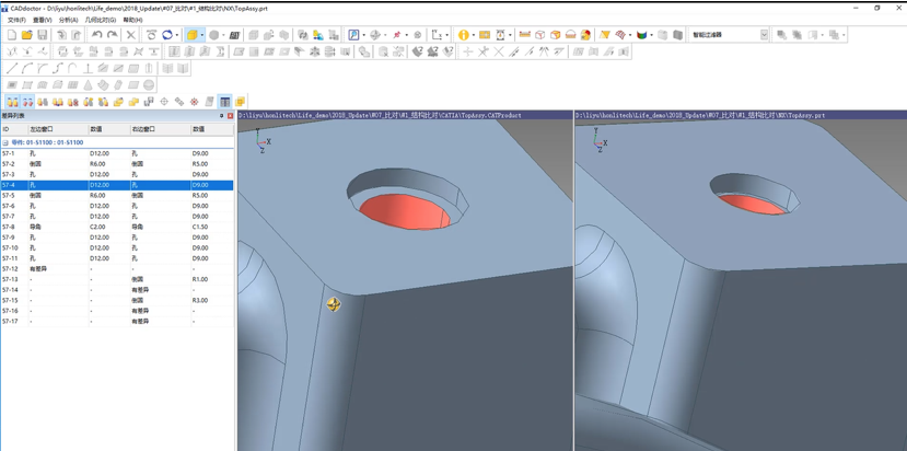
Geometric matching
The geometry comparison module of CADdoctor can find the difference of geometry of two CAD files and the difference of edge position, such as the data before and after design changes. CADdoctor can identify the radius of fillet, hole diameter and chamfer edge length, which can be quickly verified by numerical comparison. Automated report compilation includes detailed comparison data for analysis and review, which can significantly improve work efficiency. The detailed comparison module of CADdoctor can find out the topological difference information such as the surface or edge of merge and segmentation, and even the continuity of edge. The comparison results will be better checked and browsed by the user through color display.
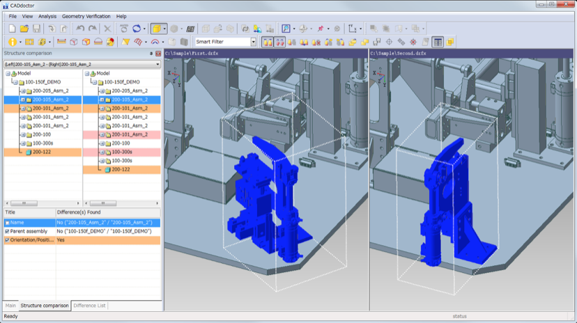
Assembly structure comparison
The geometric comparison of CAD octor can also compare the differences between two assembly structures, such as adding/deleting parts, position/direction of assembly parts, position of parts in assembly tree and part name. The difference results after comparison can be highlighted in the assembly tree, as shown in the left-hand structure comparison panel. Each difference can be checked with the enlargement function of the CADdoctor.
The CADdoctor can compare large assemblies and change the display/non-display attributes of parts in the structure comparison panel by displaying control commands. CADdoctor can find the same parts in two assemblies through some special information, such as internal number, component location and element number. CADdoctor provides the most accurate comparison function for the market.
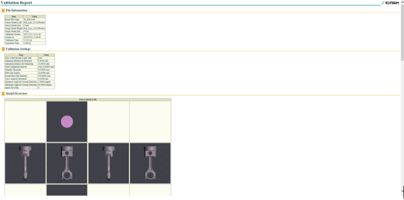
Output Comparison Report
Geometric alignment results can be exported to files in XML format, which can be viewed by most browsers. Using this report, the comparison results can be shared with other departments or business partners who do not have a CADdoctor. The comparison report contains the comparison results pictures, which can be used for rapid model review. The comparison report is also useful for checking the quality of product data. Users can quickly understand the differences between parts or surfaces that are not allowed.
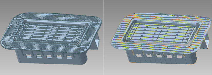
5、Quality Check for Mold Manufacturing
Quality Check for Mold Manufacturing is based on the function of injection/casting technology. Quality Check for Mold Manufacturing fuction is mainly aimed at product and designer to quickly judge the mouldability of digital models, which can shorten the data processing time in the early stage of production and reduce rework.
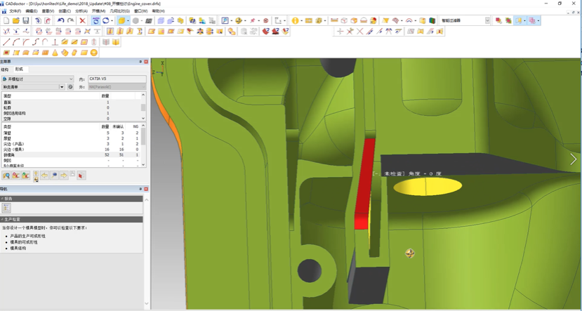
Manufacturing Process Inspection
Mold Manufacturing Check is run on 11 items in 3 categories. The first category, Product Formability, is used to check for product quality issues during or after form, such as inadequate or excessive thickness. The second category is for Mold Construction, which contains checks for undercut or slide candidates, which often leads to complex mold construction, increasing the mold manufacturing cost. The third category is Mold Formability, for the checking of such issues as sharp edge, deep trench, and small bump. These types of detected characteristics cannot be formed by the mold. By setting tolerances and thresholds based on company standards, you can ensure that every item which does not meet these standards will be detected.
Manufacturing Report Export
The results from the manufacturing check can be exported in an XML format which is viewable by most web browsers. Results can be shared with other departments or partners who do not have CADdoctor in order to facilitate design changes.
The report also includes an overall image of the model and exploded images of each issue ensuring that readers of the report can easily understand and interpret the issu
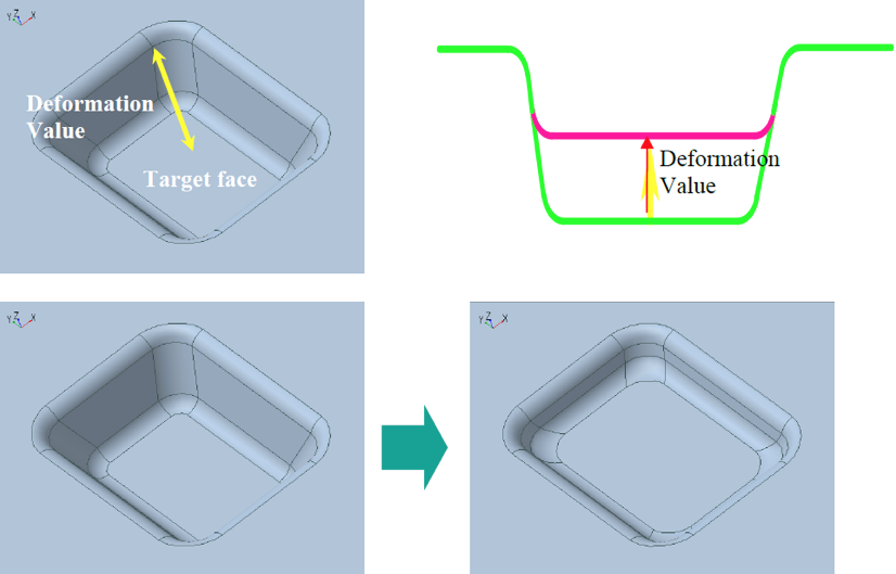
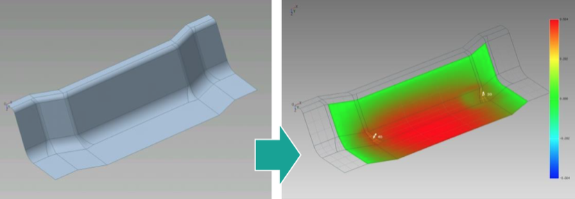
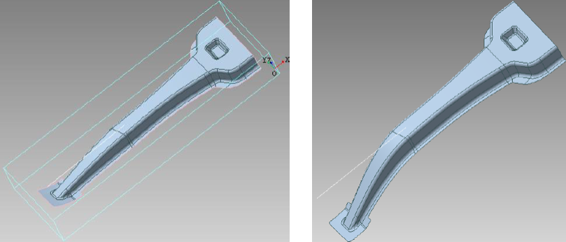
6、Sheet metal pre-deformation
CADdoctor can compensate the deformation and springback of the model by designing the following stamping model.
Large-scale deformation compensation
Bending compensation
Rotary compensation
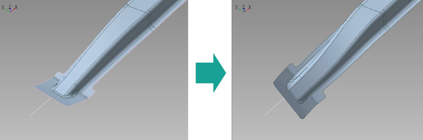
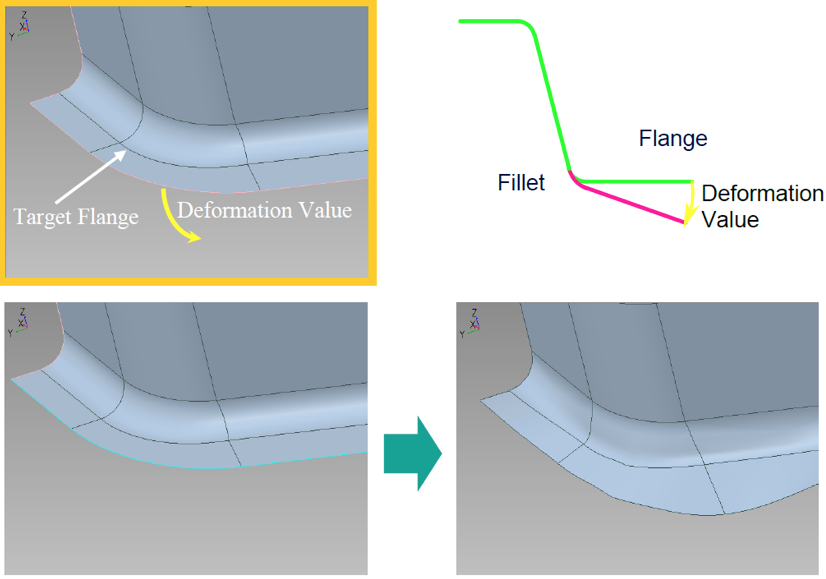
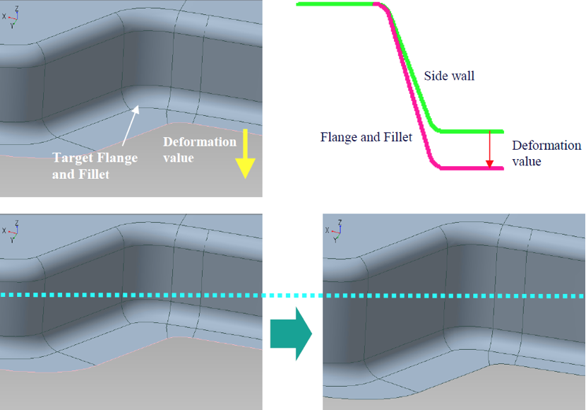
Flanging compensation
Flanging motion compensation
Drum compensation

Moving Compensation of Stamping Surface